

I had a few stepper motors salvaged from CD/DVD Drives.

So I decided to make a small Draw Bot using two of them.
It is controlled via Bluetooth.
Powered by three 3.7v LiPo batteries in series 11.1v.
power to the motors is regulated to 5v 400mA.
Controller is an Arduino NANO.
Stepper Drivers are two modified L293D driver shields.
Controller is an Arduino NANO.
Stepper Drivers are two modified L293D driver shields.
This was a nice little project to do, but.
The stepper motors from CD/DVD Drives are bipolar permanent magnet type with only 20 steps/revolution.
To get accuracy from this type of stepper, requires a gearbox.
If you watch the video you will see that errors constantly occurred.
I may make a larger version using hybrid stepper motors.
or get some of the cheap unipolar motors.
Did some code to allow for bios between the two wheels, made a big
improvement, but the motors are not strong enough to compensate for a sloping
surface.
Got two cheep geared unipolar motors to try.

Made an other Draw Bot using 2 of these motors.


Not a good chose for this type of project.
Big Fail.
There is too much backlash in the gear box.
Cannot rotate the Draw Bot accurately enough.
Didn't do a video, I think a Photo says it all.

The lower plot is the Draw Bot with the 28BYJ-48 motors.
Decided to modify how the motors drive the wheels. Moved the motors so that the wheel was not directly affixed the shaft of the motor, but was driven via a gear.
This gearing reduced the drive by 5:1 which also reduced the backlash 5.


This improved things but took 5 times longer to draw.
Too Slow.

I got some Hybrid Stepper Motors


Improved it but not perfect.
Added some code to compensate for step fractions, but still if the surface is sloping, it wanders off track.
Realized I haven't added any voltage control to the stepper motors so I added a DC-DC Buck to drop the voltage to 8.5v.
Had to keep the voltage above 8.2 volt because I am using DVR8825 drivers.
Also I am tapping of the Motor power to drive a LM7805 for the servo.


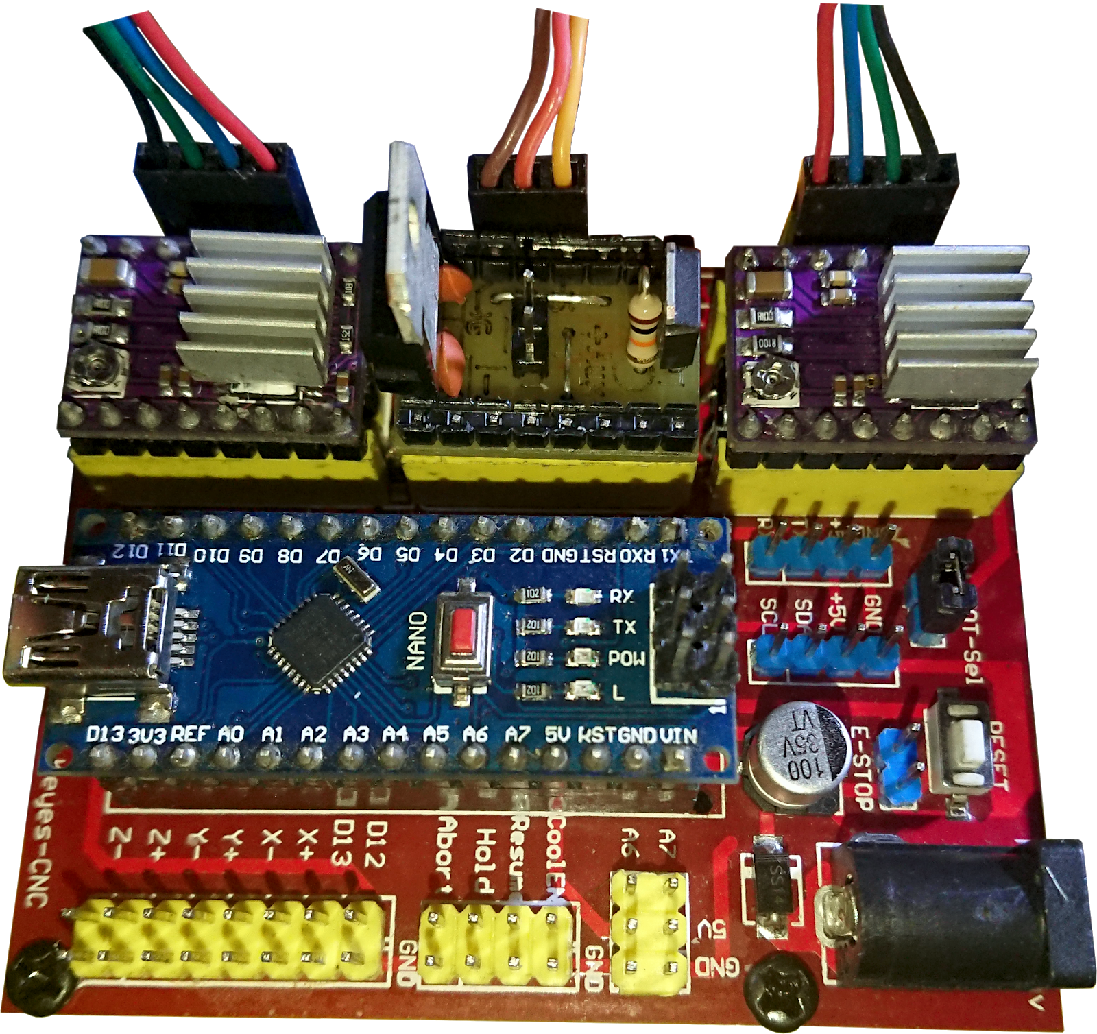
As I am using a cloned Keyes CNC Shield, I have made a driver for the Servo that fits in the Y Drive socket. Fitting the Left Hand Driver in the X Driver socket, fitting the Right Hand Driver in the Z Driver socket.

Decided to modify how the motors drive the wheels. Moved the motors so that the wheel was not directly affixed the shaft of the motor, but was driven via a gear.
This gearing reduced the drive by 5:1 which also reduced the backlash 5.


This improved things but took 5 times longer to draw.
Too Slow.

I got some Hybrid Stepper Motors


Improved it but not perfect.
Added some code to compensate for step fractions, but still if the surface is sloping, it wanders off track.
Realized I haven't added any voltage control to the stepper motors so I added a DC-DC Buck to drop the voltage to 8.5v.
Had to keep the voltage above 8.2 volt because I am using DVR8825 drivers.
Also I am tapping of the Motor power to drive a LM7805 for the servo.


Change the code I wrote for Acceleration and Deceleration.
Tested it at Full Speed and Half Speed
As I am using a cloned Keyes CNC Shield, I have made a driver for the Servo that fits in the Y Drive socket. Fitting the Left Hand Driver in the X Driver socket, fitting the Right Hand Driver in the Z Driver socket.
If you like what I have done, or want to know more.
Please leave a comment below.
Hello Tim,
ReplyDeleteI'm Phi Le, in last week, you send me schematic of driver of Servo on a cloned Keyes CNC Shield (Y axis). But how to connect 3 pins of Servo? I saw your instruction picture on this page and I guess you connect 5V - AUX of driver with Signal and VCC of servo. So where is connection GND of Servo?
Hi Phi Le,
DeleteI have done a post showing how I made and connected the driver on the CNC Shield.
https://tims-draw-bot.blogspot.com/2020/08/driver-to-control-servo-vrom-nano-cnc.html
Let me know if this is OK?
Hi,Tim Can I have a firmware? My device: Arduino NANO , 42mm Hybrid Stepper Motors ,Bluetooth hc-05. Thank you very much!anqiking88@gmail.com
ReplyDeleteHi anqi.
DeleteNice to see you are doing a similar project.
The firmware on my Hybrid version is quite complex (and a bit of a mess), I have put a lot of work into special routines, to try and compensate for drift.
I would rather not give out this code, but if you want to show me what you have so far, I will help the best I can.